Optical Transmission
The curve shows the typical optical transmission curve with the absorption edges
for GE 124 from the UV through visible into the infra-red range. In the typical
250-290nm range for UV microscopy applications the material exhibits excellent transmittance.
Fused Quartz Average Transmisstion Curves
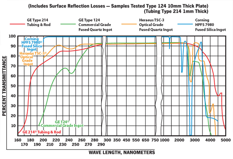
Graphs Compliments of Supplier
Surface Finish
Our slides and coverslips have a surface flatness of ±1 degree, with 60/40 scratch/dig specification. 60/40 scratch/dig has the following definition:
Visibility Method
Scratch/Dig: Surface quality is specified by a number such as 60/40. The 60 defines a scratch width according to a visual standard (it does not mean a scratch can be 60 um wide). For reference, scratch numbers of 60 typically refer to maximum allowable scratch widths of ~7um to 8um. With this in mind, the scratch part of the specifications includes the following four requirements:
- The combined length of the scratches with the specified scratch number shall not exceed 25% of the smallest dimension of the clear aperture.
- When scratches with the maximum allowable scratch number are present, then the sum of the products of the respective scratch numbers times the ratio of their length to the smallest dimension of the clear aperture for all scratches cannot exceed 50% of the maximum allowable scratch number.
- When scratches with the maximum allowable scratch number are not present, then the sum of the products of the respective scratch numbers times the ratio of their length to the smallest dimension of the clear aperture for all scratches cannot exceed the maximum allowable scratch number.
- Surface with scratch letter requirements between 10 and 20 can have no more than 4 separate scratches in any 0.25 inch circular area.
The second number of the Scratch-Dig specification refers to digs, and establishes a limit to the actual size (diameter) of the digs in hundredths of a millimeter. The dig part of the specifications includes the following three requirements:
- The maximum number of digs must be less than 1 per 20mm diameter circle.
- For every 20mm diameter clear aperture, the sum of the diameters of all digs exceeding 2.5um in diameter cannot exceed 2 times the specified dig letter.
- Digs with a dig number less than 10 must be at least 1mm apart.
60/40 equates to a Ra of 0.16u (40Å)
| Scratch/Dig |
Angstroms Ra |
Microinches Ra |
| 10/5 |
10A |
0.040u" |
| 20/10 |
20A |
0.080u" |
| 40/20 |
30A |
0.12u" |
| 60/40 |
40A |
0.16u" |
| 80/50 |
50A |
0.2u" |